SENEVEN® Permanent Leak Location System (PLLS)
Continuous geoelectrical monitoring of geomembrane lining systems with automatic leak localisation and threshold-based alerting—24/7 over the service life of the asset, to ASTM D8551.
Engineering Background
The SENEVEN® Permanent Leak Location System (PLLS), developed by SENEVEN Technology (Shanghai), is a continuous, automated leak-location and integrity-monitoring solution for geomembrane lining systems. Sensors and cables are pre-installed above and below the primary liner during construction; once energised, the system performs round-the-clock acquisition of electric-potential and current-density data, applying ASTM D6747-class electrical leak-location principles continuously rather than as a one-off post-construction survey. The system is designed, installed and commissioned in accordance with ASTM D8551, Standard Practices for Permanent Monitoring Systems for Electrical Leak Detection and Location, in the point-sensor configuration of §5.2.1. An optional chemical-signature channel records the conductivity of any infiltrating leachate or process liquid, refining localisation. Owners can configure the system in electrical-only, chemical-only or dual-mode operation to match the chemistry, geometry and risk profile of each project.
- Continuous, 24/7 unattended operation throughout the service life of the lining system
- Built to ASTM D8551 — point-sensor grid, artificial-leak functionality testing and site-response-current logging
- Dual-parameter acquisition—synchronous electric-field and conductivity channels
- Pre-installed embedded sensor network—multi-parameter sensing nodes coupled to a conductive geotextile carrier
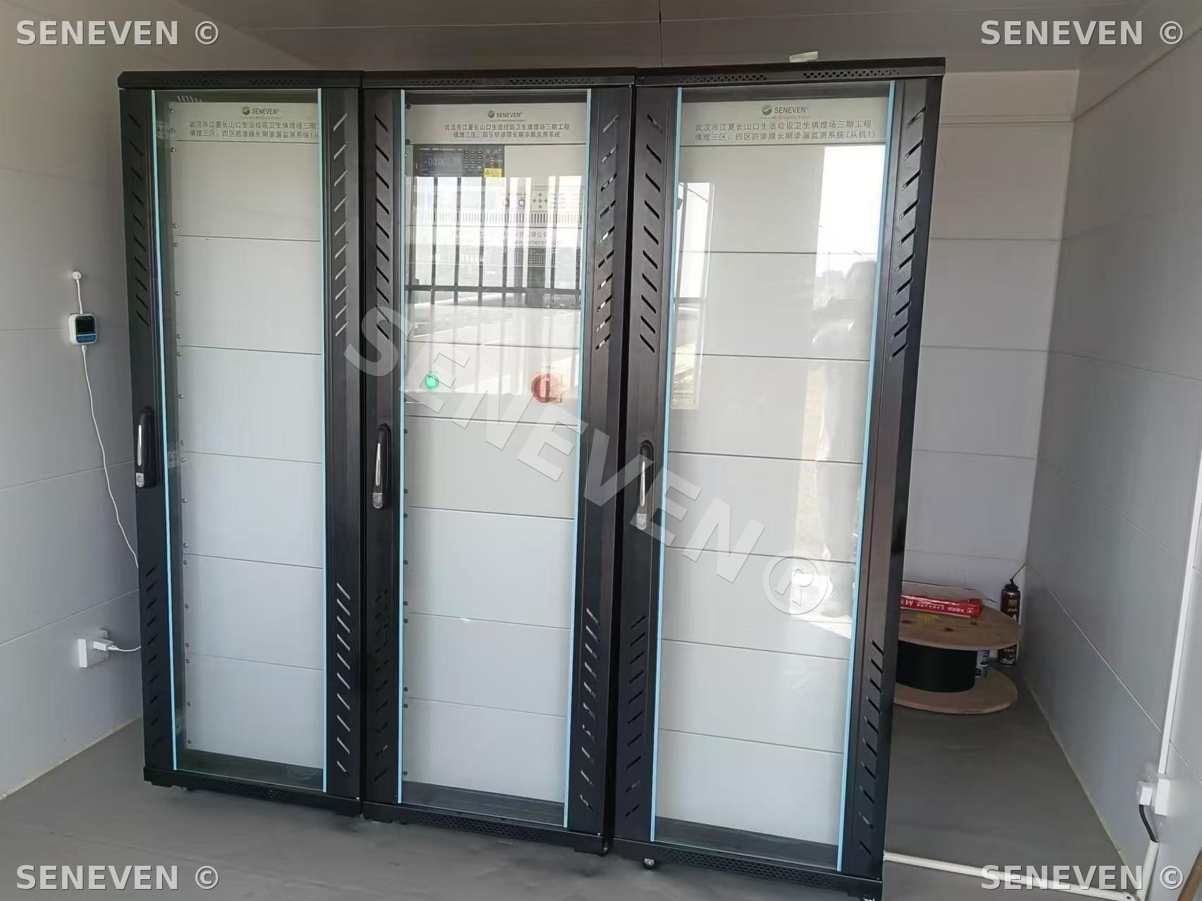
- 19-inch rack-mounted acquisition and control cabinet with fault-tolerant power management and high-precision data acquisition
- Cloud-based analytics with automatic leak-coordinate computation and 2-D / 3-D potential-field visualisation
- Threshold-based alerting—exceedances trigger automated notifications to operations personnel
- Full-lifecycle data management—real-time acquisition, archival, audit logging and operator dashboards
Principle & Method
The PLLS combines two complementary measurement modalities.
1. Electrical leak location. The geomembrane behaves as a near-ideal dielectric between two conductive media. The system establishes a controlled potential difference across the liner; an intact membrane sustains a uniform far-field distribution while any breach creates a local low-resistance path that perturbs the field. Reference and roving sensor pairs sample the resulting equipotential anomalies, and inversion algorithms map their spatial signature to leak coordinates.
2. Chemical-signature monitoring. Smart sensing electrodes installed beneath the liner respond to the conductivity—and other electrochemical parameters—of any liquid that reaches them. A step change in conductivity at a given sensor flags both the occurrence and the approximate location of leakage and is fused with the electrical-channel result to improve overall localisation accuracy.
Continuous integration of these two data streams over time turns a passive lining system into an instrumented, self-reporting asset, providing the evidentiary basis for targeted investigation and repair.
Typical Scenarios & Diagrams
System Principle
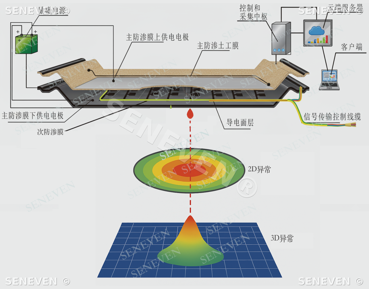
When the geomembrane is breached, current passes through the upper membrane into the conductive geotextile, which carries the signal to the sensing electrodes. The acquisition system reads that signal and the analysis software decides whether a leak exists and computes the coordinates of the defect.
Operating principle of the SENEVEN® Permanent Leak Location System.
1. Electrical leak location. The geomembrane behaves as a near-ideal dielectric. A controlled electric field is impressed across the liner via electrodes installed above and below the membrane. An intact liner yields a uniform potential distribution; a breach forms a local low-resistance current path that distorts the field. Reference and roving sensor pairs sample these equipotential anomalies, and inversion algorithms map their spatial signature to leak coordinates.
2. Chemical-signature monitoring. Smart sensing electrodes installed beneath the liner respond to the conductivity—and other electrochemical parameters—of any infiltrating liquid. A step change in conductivity flags the occurrence and approximate location of leakage; fusion with the electrical-channel result improves overall localisation accuracy.
By continuously combining electrical and chemical observations and analysing the data record over time, the system delivers georeferenced leak coordinates and a defensible audit trail for investigation and repair.
System Composition
The SENEVEN® Permanent Leak Location System (PLLS) is a fully integrated continuous monitoring solution for geomembrane lining systems, providing all-weather, online integrity surveillance and automatic leak localisation.
Acquired data streams. Pre-installed sensor pairs above and below the primary geomembrane acquire electric-potential and current-density data continuously, supporting real-time integrity assessment of the liner system. The optional chemical-signature channel records the conductivity of any infiltrating liquid and is fused with the electrical record to refine localisation.
Subsystems and functions: • Embedded monitoring units — multi-parameter sensors, conductive geotextile carrier, and signal-transmission and control cabling, pre-installed above and below the geomembrane for distributed acquisition. • Acquisition and control cabinet — power supply, fault-tolerant power-control module, acquisition and control modules, high-precision data-acquisition unit and master server, integrated in a standard 19-inch rack; delivers high-sensitivity electrical and chemical-signature acquisition with real-time uplink to the cloud analytics platform. • Data-analytics software — automated supply-and-acquisition control, leak-location inversion to compute leak coordinates, alert dispatch to designated personnel, and full data read-back, archival and lifecycle management. • Auxiliary works — civil and electrical infrastructure that supports stable operation of the monitoring system over the design life.
System layout and interpretation flow: source electrodes and a conductive layer sit between the primary and secondary liners; signals travel by cable to the acquisition host and on to the cloud, where a leak appears as a 2-D anomaly ring and a 3-D anomaly peak.
2-D Equipotential Map
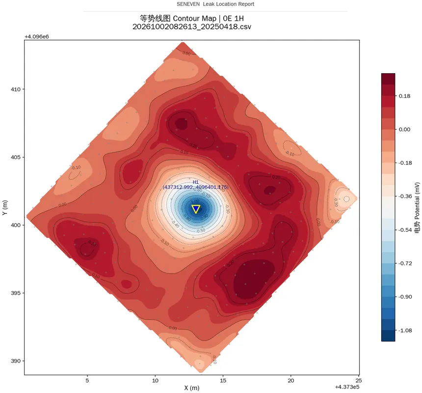
The cloud platform samples the whole field on a set schedule and inverts it into a 2-D equipotential map. With an intact liner the contours stay smooth and evenly spaced; once a breach forms it acts as a point source and the contours close into a ring whose centre gives the plan coordinates of the leak. Maps and coordinates are archived together for round-to-round comparison and excavation verification.
A 2-D equipotential map as the platform outputs it; the triangles and inverted triangles are the computed leak coordinates.
3-D Potential Surface
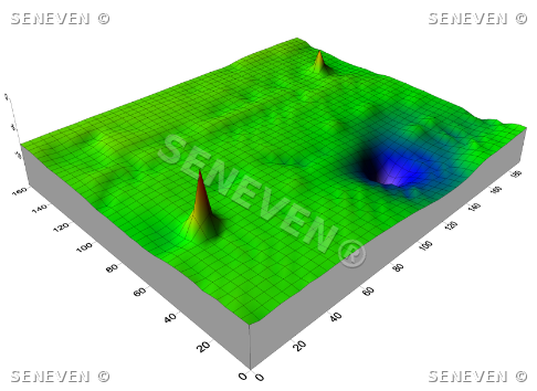
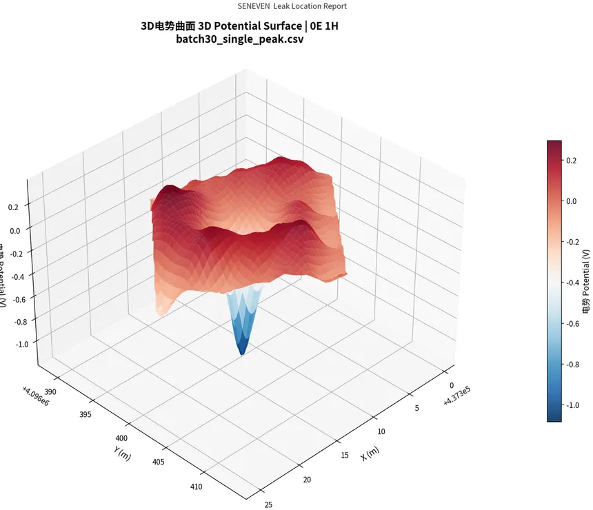
The system continuously samples potential at the sensor-electrode array and reconstructs the 3-D potential field on the cloud platform. An intact liner produces a smooth, near-uniform field; a defect creates a local low-resistance path, presenting itself as a sharp peak in the surface plot.
Inversion of the equipotential anomaly returns leak coordinates with centimetre-level accuracy, visualised in 2-D / 3-D for the operations team. Combined with threshold-based alerts and full-lifecycle archival, every leak becomes a quantifiable, auditable engineering record.
The 3-D potential surface for the same site at the same epoch: peak position gives the coordinates, peak height the severity of the leak.
Why Permanent Monitoring
Why Monitor for the Long Term
A one-off survey certifies the state of the liner on the day it goes into service. The risk to that liner, however, runs for the whole life of the works.
Differential settlement, material ageing, later construction work and accidental puncture can each open a new breach at any point during operation. The permanent monitoring system is embedded together with the liner during construction, samples continuously around the clock once in service, and raises an alarm with computed coordinates the moment a leak appears.
It should be said plainly that operational-phase monitoring and post-construction survey are two independent technical routes. They differ in electrode layout, in how the field is established, in interpretation logic and in what they deliver. Each belongs to its own project phase, and neither substitutes for the other.
What the System Delivers
Timely response
An alarm is raised in the first hours of a leak, while it can still be dealt with before the plume spreads.
Definite location
Leak coordinates are delivered directly, so no blind excavation is needed — repair cost and downtime drop sharply.
Regulatory support
Meets the supervisory requirements of GB 18598-2019 and related standards for hazardous and general industrial solid waste landfills.
Defensible evidence
A monitoring operation report is issued annually or as required, serving as the basis for environmental inspection and compliance audit.
What a monitoring system really changes is when a leak is found. Without one, the leak is not noticed until the groundwater wells turn anomalous — by which point the plume has formed, neither the location nor the duration of the leak can be established, and the site is usually left with wholesale excavation or years of groundwater remediation. With one, the same breach triggers an alarm within hours, and comes with coordinates.
Standard Conformance
Built to ASTM D8551
The Permanent Leak Location System is designed, installed and commissioned in accordance with ASTM D8551, Standard Practices for Permanent Monitoring Systems for Electrical Leak Detection and Location.
Point-sensor configuration
The system is a grid of point sensors pre-installed beneath the geomembrane — the point-sensor configuration of ASTM D8551 §5.2.1, not a zonal (mesh-pad) sensor system. Every sensing electrode is wired individually to the acquisition host and its position registered as X–Y coordinates.
Artificial leak and functionality testing
An artificial leak is installed before the geomembrane is placed and is used to calibrate and verify both method and equipment. Once in service it can be connected or disconnected at any time to confirm the measurement circuit still works — without cutting a real hole in the liner.
Site response current logged
Every round of measurement logs the site response current with the artificial leak both connected and disconnected, and the figures go into the monitoring report as objective evidence that the measurement circuit is still sound.
Mobile survey before commissioning
A mobile leak location survey is carried out before the facility goes into service, to clear the holes made during construction: the exposed liner is surveyed by the arc testing method (ASTM D7953) and, after covering, re-measured by the dipole method (ASTM D7007 / D8265).
On the life of buried components. ASTM D8551 requires every buried component to outlast the geomembrane it monitors. The sensing electrodes, source electrodes, cabling and all connections are non-metallic conductive material; the embedded components last as long as the geomembrane they monitor.
Cloud Platform
The Cloud Platform
The cloud platform carries the analysis and management side of the system. The maps above are what it outputs.
- 01
Scheduled & on-demand acquisition
Acquires on a set schedule, and a survey can also be launched remotely at any time.
- 02
Multi-algorithm cross-validation
Several in-house algorithms cross-check the data across both the time and the space dimension.
- 03
Maps & trend output
Results are rendered as 2-D equipotential maps, 3-D surfaces and historical trend curves.
- 04
Instant alerting
Once an anomaly is confirmed, alerts go out by email and SMS with leak coordinates, time of occurrence and the supporting data.
Data from the entire life cycle is archived and traceable, meeting the evidentiary requirements of environmental audits and third-party review.
Technical Characteristics
No damage to the primary liner
Fully sealed, non-metallic flexible sensing electrodes are laid without breaching the geomembrane, and resist ageing and electrochemical corrosion for the life of the works.
Addresses the missing conductive layer in double liners
A purpose-made conductive geotextile solves the problem of conventional double-liner structures (such as twin HDPE membranes), where the absence of a conductive layer under the upper membrane made monitoring impossible.
Corrosion-resistant connections
Signal cables are fully sealed where they meet the sensing electrodes, so metal conductors cannot electrolyse or corrode — this is where long-term monitoring systems most often fail.
Fast response
An alarm is raised at the earliest stage of a leak, buying time for emergency repair.
Usable as compliance evidence
A monitoring operation report is issued annually or as required, for environmental inspection and compliance audit.
Interpretation Rules
The difficulty of the electrical method lies not in measurement but in rejecting interference. Over years of practice these interpretation rules have been fixed as inviolable constraints, written into both the algorithms and the field work instructions. They are deliberately conservative, with a single purpose: every coordinate reported must correspond to a real defect once excavated.
- 01Source electrode as validity check
After each current injection the maximum positive peak of the field must fall near the source electrode used. If it does not, the data set is void and must be re-acquired.
- 02Upper and lower liners read separately
In a double HDPE structure the upper and lower liners are energised and interpreted separately, so that signals from one layer cannot be mistaken for the other.
- 03Near-field detections discarded
Any detection within one electrode spacing of the source electrode is discarded: field strength there is inherently high and the response cannot be attributed to a leak rather than the source.
- 04Confirmed versus suspected
Three source electrodes or three methods hitting the same point, with positional spread no greater than the electrode spacing, is graded confirmed; two hits is graded suspected.
- 05Unpowered electrodes masked out
Electrodes whose supply circuit is not closed cannot count as corroboration; otherwise a suspected point with only two pieces of evidence would be wrongly promoted to confirmed.
Dual-Channel Interpretation
The electrical channel returns the coordinate and the chemical channel supplies a second, independent confirmation; only the two together make a decision that can be audited.
| Channel | How it works | Role |
|---|---|---|
| Electrical | Exploiting the insulating property of the liner, a field is established above and below it. An intact liner gives a relatively even distribution; a hole forms a local low-resistance path and the field changes abruptly. Proprietary inversion algorithms analyse the anomaly and solve for coordinates. | Primary evidence — returns the leak coordinate |
| Chemical tracing | The latest sensing electrodes integrate conductivity and other parameters. When leachate reaches an electrode its chemical signature shifts abruptly, giving the electrical channel a second confirmation. | Secondary evidence — confirms the leak and helps gauge extent and severity |
Components & Layout
Components and Layout Parameters
| Component | Make-up and function |
|---|---|
| Sensing electrodes | Acquisition terminals that carry the characteristic signal to the data-acquisition host. Made of non-metallic conductive material, with biochemical corrosion resistance comparable to the geomembrane itself. |
| Signal cables | High-strength anti-corrosion cable with a flexible protective sheath, high tensile strength and long service life. |
| Non-metallic source electrodes | Corrosion-resistant conductive polymer, resistant to acid and alkali, source electrodes used to energise above and below the geomembrane. |
| Conductive geotextile | Engineered electrical parameters that guarantee reliable readings at the sensing electrodes, with good ageing and chemical resistance. |
| Acquisition & control host | Power supply, power-source control module, acquisition control module, channel-switching matrix and host computer, integrated in a standard 19-inch cabinet. |
| Acquisition & analysis software | Automatic power-source control and data acquisition, leakage computation, leak coordinates and alerting to designated staff; with data retrieval and archiving. |
Layout
Sensing electrodes (point sensors, ASTM D8551) are laid below the geomembrane in a grid array; spacing is typically 1–6 m, set by risk level and the required location accuracy. Location accuracy reaches the centimetre level and never exceeds half the electrode spacing.
Cabling
Each sensing electrode is wired individually back to the acquisition host, which avoids cross-talk and shared-line failure.
Data link
Electrical and electrochemical data are acquired in real time; the cloud platform processes the readings and presents anomalies as 2D or 3D plots with leak coordinates.
On non-metallic materials. The environment beneath a landfill liner is strongly corrosive over the long term. Metal electrodes and exposed metal joints electrolyse and corrode within a few years — the system keeps running, but the data is no longer trustworthy. Sensing electrodes, source electrodes and every connection are therefore non-metallic conductive material, which is what lets the embedded components last as long as the geomembrane they monitor.
Track Record
Completed Monitoring Projects
All of the projects below are fixed, permanently installed online leakage monitoring systems.
- 01Xi’an Solid Waste Comprehensive Treatment Site, Phase I — online monitoring system
- 02Huludao Industrial Waste Treatment & Disposal Centre — real-time liner monitoring system
- 03Wuhan MSW Landfill, fly-ash secure disposal zone — long-term leakage monitoring system
- 04Mianyang Industrial Solid Waste Centre, secure landfill — long-term geomembrane leakage monitoring
- 05Wuhan Jiangxia Changshankou MSW Landfill, Phase II — long-term geomembrane leakage monitoring
- 06Zhangye Hazardous & Solid Waste Disposal and Recycling Centre — long-term geomembrane leakage monitoring
- 07Binzhou Beihai Weiqiao Hazardous Waste Disposal Site, Shandong — long-term leakage monitoring
- 08Huazhou Fly-Ash Treatment Project — long-term liner leakage monitoring system
- 09Shenhua Yulin Coal Utilisation Project, Stage I — long-term online geomembrane leakage monitoring
- 10Northern Guangdong Hazardous Waste Centre, secure landfill — online leakage monitoring system
- 11Shenhua Yulin Coal Utilisation Project — long-term online geomembrane leakage monitoring
- 12Guannan Fly-Ash Landfill — fixed long-term online geomembrane leakage monitoring
- 13Sino-Environment Secure Landfill, Phase I Zone II — fixed long-term online geomembrane leakage monitoring
These projects span six regions of China and cover municipal solid waste, incineration fly ash, hazardous waste, industrial solid waste and coal-chemical residues. Corrosivity and conductivity differ markedly between these media, so electrode material and interpretation thresholds have to be adjusted accordingly — parameters that cannot be read off a standard and are only accumulated project by project.
Need technical support?
Contact the SENEVEN engineering team for a tailored detection or monitoring scope, scaled to your project type, footprint and field conditions.